


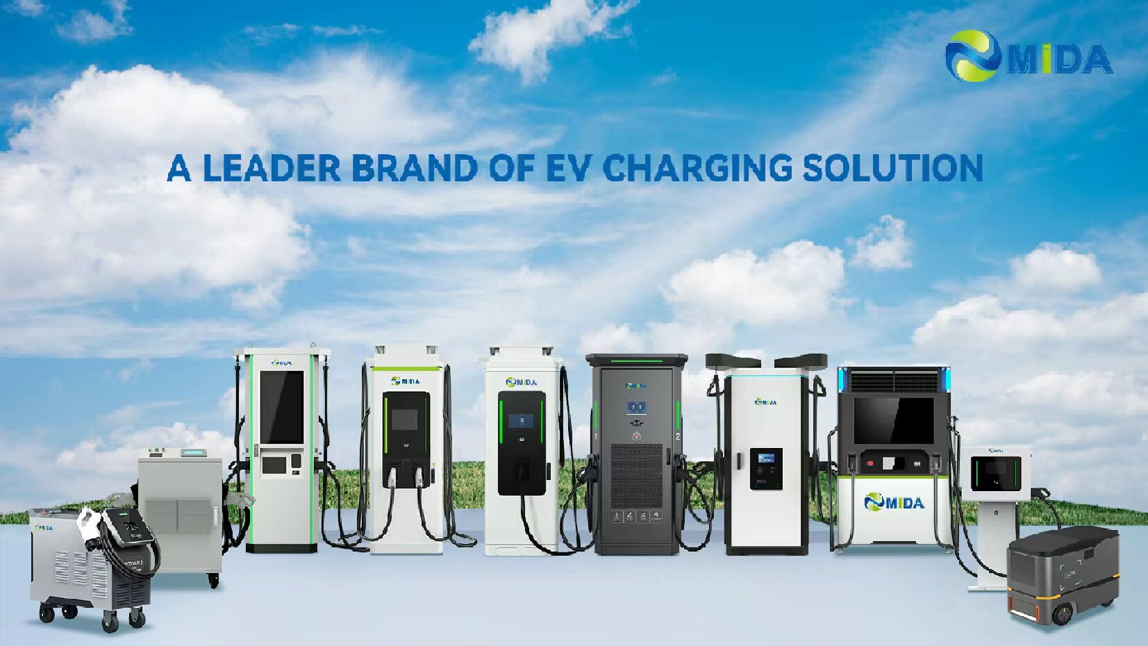
Quick Answer: Smart solar DC fast charging station
The Smart Solar DC Fast Charging Station with BESS, OCPP 1.6J, and Load Management is a solar-integrated DC fast charging solution for site owners and operators with constrained grid capacity. It combines solar-ready power conversion, battery energy storage system (BESS) and a centralised energy management layer, so a site can deliver dependable DC charging while keeping demand within the limits its electrical supply can support. Storage buffers the load profile, energy management decides where each kilowatt comes from, and the platform stays manageable through standard charging protocols. Because operating conditions vary widely, the final power stage, connector layout, storage capacity and thermal design are all settled at configuration stage for the specific site.
Key Takeaways
- Solar-ready architecture: designed for integration with on-site photovoltaic generation and coordinated by one control layer.
- Storage buffering: battery energy storage system (BESS) smooths site demand and supports high-power charging at constrained locations.
- Managed operation: remote monitoring, access control and configuration across the station fleet.
- Flexible configuration: power, connectors and thermal design confirmed per project requirement.
- Commercial durability: built for daily, high-utilisation charging duty in public and fleet environments.
- Scalable deployment: capacity can be staged as utilisation and generation grow at the site.
Product Design and Configuration Overview
Overall Design: How the Station Is Built
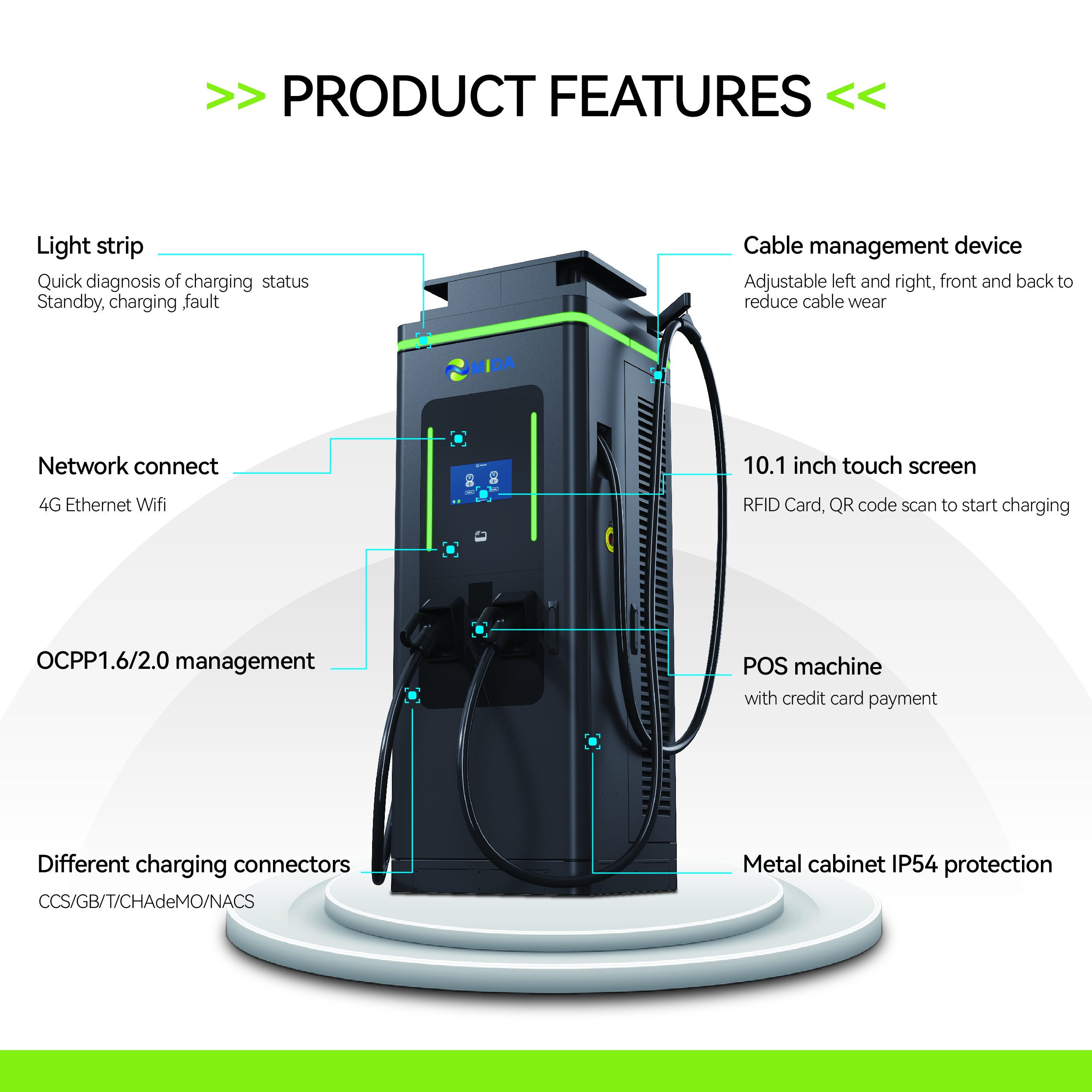
The station is laid out as a commercial charging asset rather than a piece of equipment bolted onto a wall. A single enclosure houses the power conversion stage, the control electronics and the interface that drivers actually touch, which keeps cable runs short and servicing access straightforward. The pedestal or cabinet format is intended for outdoor installation, with mounting, foundation and cable entry agreed during the site survey so the finished arrangement looks deliberate rather than adapted.
Front access is a design priority. Filters, connectors and serviceable components can be reached without dismantling the enclosure, which reduces the time an installation is offline and keeps routine inspection within normal maintenance windows. Where the site layout calls for a different arrangement, cabinet and satellite options exist, and the exact combination is confirmed against the configuration selected by the operator.
Charging Method: From Arrival to Session Start
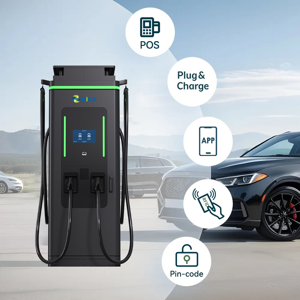
Charging starts with identification. Driver authentication, fleet card access or an authorised mobile flow unlocks the session, and the station then negotiates with the vehicle to establish the charging profile it can accept. Power is delivered at DC through the configured connector type, and connector type and count depending on configuration so the station can match a mixed vehicle fleet without redesigning the installation.
While the session runs, the controller continuously reconciles three inputs: the request from the vehicle, the limit available from the site supply and the energy stored in the battery system. Where a limit is reached, the station adjusts output instead of failing the session, and stored energy can be brought in to hold charging power at a usable level. Cable management, connector holsters and a clear session summary on the screen complete the driver experience.
Product Advantage: Why Operators Choose This Platform
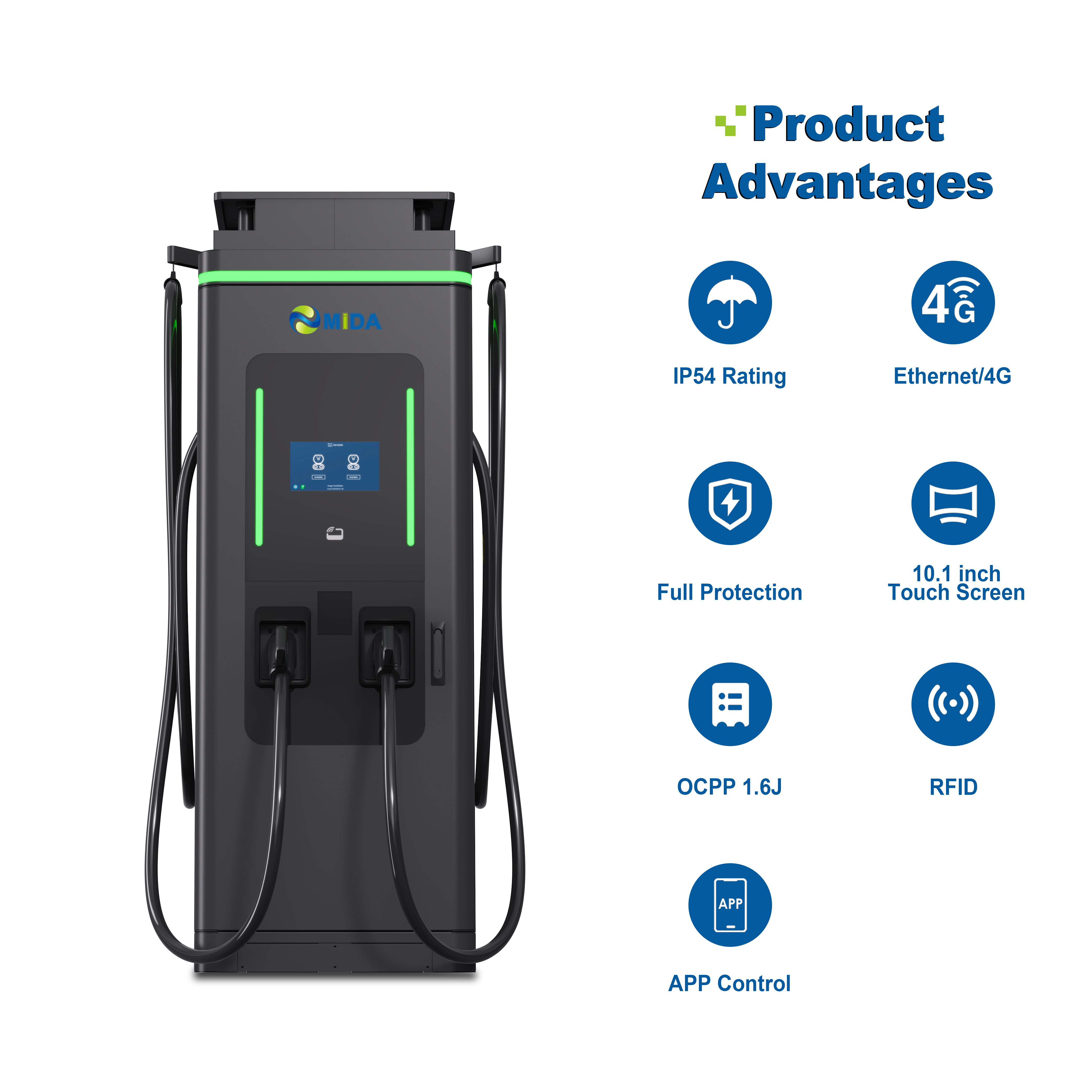
The commercial case rests on three things: charging availability, control over demand and a route to using on-site generation. Energy storage and load management work as a pair: the controller monitors site consumption, storage state and active sessions, then modulates charging power or discharges stored energy to hold the site within its ceiling. Because control runs through OCPP 1.6J, operators keep visibility and remote configuration inside their existing management stack.
On the technical side, the power stage is built for repeated high-power cycles rather than occasional use, and cooling to be confirmed against the required duty cycle manages heat across the duty cycle. That combination allows operators to schedule charging around vehicle availability instead of tiptoeing around thermal limits, and it keeps the driver experience consistent through the working day.
Residential and Commercial Use: Matching the Site to the Duty
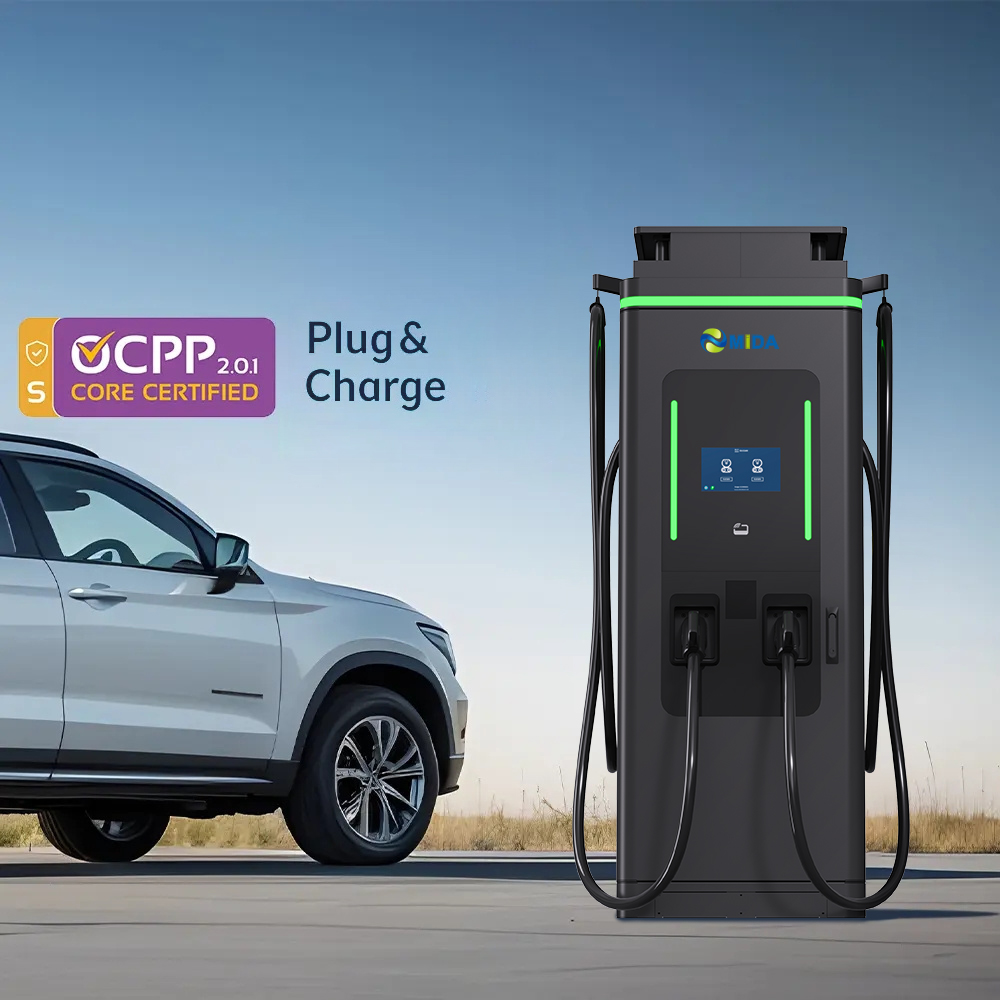
The primary applications are commercial. The station fits workplace campuses, retail locations, depots and mixed-use developments where building load and charging load share one supply. Building managers can define priority rules so essential site functions are protected, while drivers still receive a working session.
On lighter-duty sites, the same platform can serve mixed residential and commercial developments where residents, visitors and small fleets share a charging area. Capacity for those installations is modest by comparison, and the configuration is adjusted so the station serves its share of demand without overwhelming the building supply. In every case the electrical assessment comes first, and the final specification follows the load profile rather than the other way around.
Screen Configuration: The Operator and Driver Interface
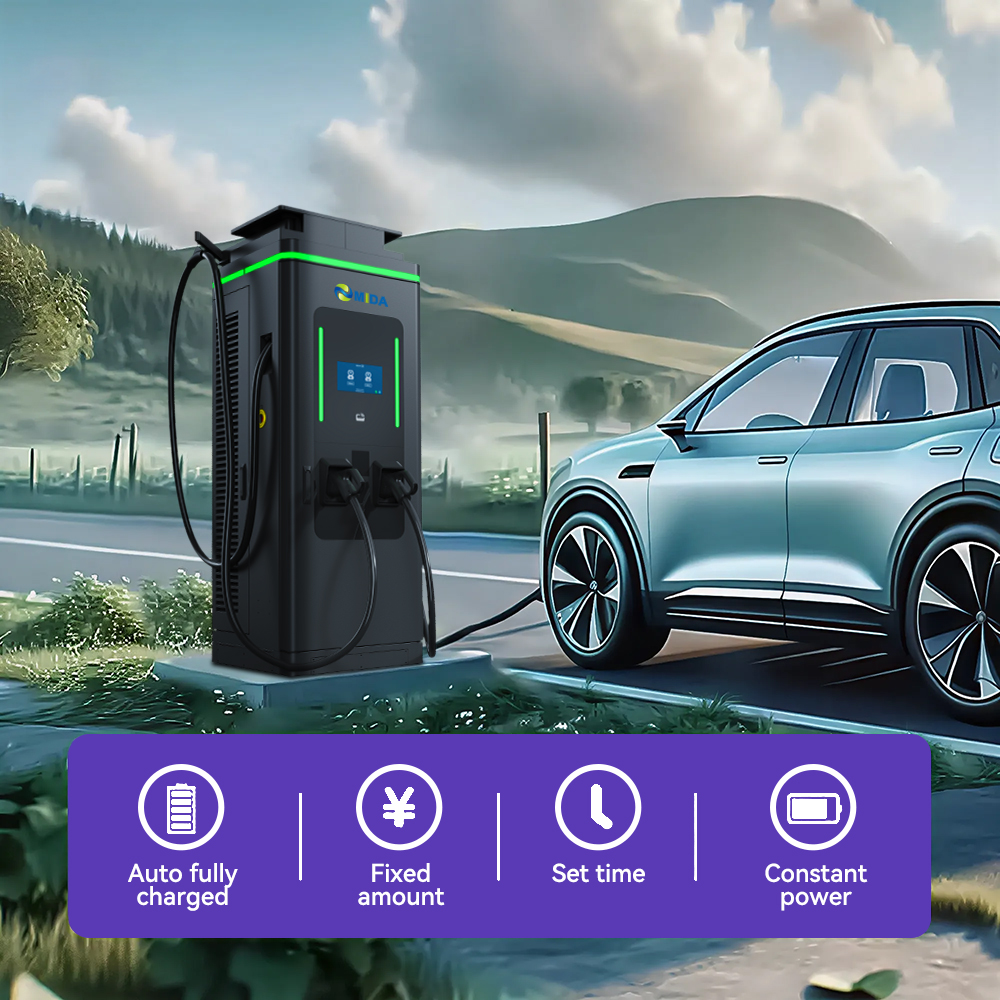
The display is the part of the station most people judge it by. A sunlight-readable interface presents instructions in clear steps, confirms the connector in use, shows session status and presents the information a driver needs to start and stop charging without assistance. Language options, brightness and the amount of on-screen detail can be configured so the unit suits local drivers rather than a generic template.
Behind the screen sits the operator layer. Consumption data, session history, fault events and energy flows between solar input, storage and vehicles are recorded for reporting and troubleshooting. Where the station is controlled through an OCPP-compatible back office, that information is also available remotely, and the exact set of available fields depends on the protocol version enabled and the capabilities of the management platform in use.
Charging Standards: Compliance and Interoperability

Interoperability is treated as a configuration decision rather than a fixed assumption. Connector standards, communication protocols and payment integrations are confirmed against the market where the station will operate, so the finished unit works with the vehicles and back-office systems actually present on site. connector type and count depending on configuration and the protocol version enabled is matched to the operator platform.
Protection and safety functions are built into the charging path, covering the interfaces between the station, the vehicle and the site supply. Certification and compliance documentation are project-specific: the applicable standards, marking and test evidence are to be confirmed with the selected configuration and destination market before delivery, and should be reviewed with the installing contractor as part of the electrical approval process.
Technical Specifications
The table below summarises the platform. Values marked as to be confirmed are deliberately left open because they depend on the configuration selected for the project, the destination market and the site supply conditions. They are finalised during technical review rather than assumed from a catalogue.
| Rated Output Power | To be confirmed for the selected configuration |
|---|---|
| Charging Type | DC fast charging with solar-ready input and energy storage integration |
| Energy Storage | battery energy storage system (BESS) |
| Connector Options | connector type and count depending on configuration |
| Input Supply | Three-phase AC site supply; the exact supply rating depends on configuration and site conditions |
| Output Voltage Range | Depending on configuration and to be confirmed during technical review |
| Output Current | Depending on configuration and to be confirmed during technical review |
| Cooling | cooling to be confirmed against the required duty cycle |
| Energy Management | Coordinated control of solar input, battery storage and charging output with load limiting |
| Protocol Support | OCPP-based management; the enabled version is confirmed per project |
| User Interface | Sunlight-readable display with configurable language and session information |
| Authentication | Driver authentication and access control according to the operator platform |
| Monitoring | Remote monitoring, session reporting and fault notification where the back office supports it |
| Enclosure | Outdoor commercial enclosure with weather protection for the installation environment |
| Mounting | Floor-mounted cabinet or pedestal arrangement; final layout confirmed during the site survey |
| Storage Capacity | To be confirmed against the site load profile and charging schedule |
| Certification | Market-specific certification to be confirmed before delivery |
| Dimensions and Weight | To be confirmed for the selected configuration |
| Operating Temperature | Dependent on configuration and installation conditions; to be confirmed |
| Warranty and Service | Service intervals and warranty terms agreed in the supply contract |
How Solar Generation and Battery Storage Work Together
Solar integration is best understood as a supply-side arrangement rather than a feature of the charger alone. On-site photovoltaic generation feeds the site, the battery system stores energy when production exceeds immediate demand, and the energy management layer decides minute by minute how much of each charging session is met from generation, from storage or from the grid. The station does not need to be told in advance what proportion that will be, because the balance is calculated continuously as conditions change.
Battery storage performs two distinct jobs. The first is buffering, which limits how much demand the charging station presents to the site supply at any moment and therefore reduces exposure to peak demand. The second is time shifting, which moves energy purchased or generated in one period to another period where it is more valuable. Both are controlled by the same layer that governs charging output, which is why a coordinated package is more useful than separate devices operating independently.
This arrangement also gives projects a phased route forward. A site can begin with the station and a modest battery capacity, prove the operating pattern, and add generation or storage in later phases as utilisation targets develop. None of that requires replacing the charging platform, because solar and storage capacity are variables in the same system design.
Deployment Scenarios
Site owners and operators with constrained grid capacity
For this audience the decisive question is whether charging can be delivered on schedule without exceeding the electrical capacity the site already has. Storage buffering plus load-aware control usually answers it, and capacity can be staged as requirements become clearer. The configuration is then matched to the vehicles actually in service.
Public and Mixed-Use Sites
Public locations need simple, self-service operation and reliable availability. Authentication, tariff rules and access rights are managed through the charging platform, allowing public drivers and authorised users to share the same hardware under different commercial terms while keeping utilisation data separate.
Constrained or Phased Sites
Where grid reinforcement is slow, expensive or uncertain, the station can be introduced at a capacity the supply can support today. Storage covers peaks, so the site delivers a useful charging service now and grows as the supply is upgraded, with the same platform in place throughout.
Why Choose This Solar DC Charging Station
- Coordinated system design: generation, storage and charging are managed as one asset rather than three separate products.
- Lower exposure to peak demand: storage absorbs the spikes that make high-power charging expensive to serve.
- Solar-ready from day one: the architecture anticipates photovoltaic integration without a hardware replacement.
- Manageable fleet: standard protocols and remote monitoring keep the station inside existing operating processes.
- Configuration on evidence: power, storage and connectors are specified against a real site profile instead of a fixed template.
- Serviceable design: front access and clear diagnostics reduce downtime and maintenance effort over the asset life.
Installation, Commissioning and Service
Deployment begins with a site survey covering supply capacity, cable routing, foundation requirements, access for service vehicles and the position of any existing or planned generation. Concurrently, the charging profile is agreed: which vehicles will charge, when, for how long, and what the site must never exceed. Those two inputs determine the configuration that is ordered, which is why the specification is finalised after assessment rather than before it.
Commissioning verifies insulation, earthing, protection settings, load limits, storage behaviour and communication with the operator platform. Staff are briefed on driver support and fault escalation, and service intervals are set against the duty cycle. Because the station reports consumption and fault data, service visits can be planned around evidence rather than a fixed calendar.
Frequently Asked Questions
FAQ 1: What is the difference between an ordinary DC fast charger and a solar DC charging station?
A solar DC charging station is designed to work with on-site generation and, in most configurations, battery storage. The energy management layer coordinates how much energy comes from solar, storage and the grid, so charging demand can be served without exceeding the limits of the site supply.
FAQ 2: What does Configurable high-power DC output refer to on this model?
It describes the DC output class of the station platform. The power actually delivered in a session depends on vehicle capability, state of charge, ambient conditions and the site limits configured at commissioning.
FAQ 3: What does load management control?
The controller regulates total site demand by adjusting charging power and discharging storage as needed, based on limits agreed with the site owner and utility.
FAQ 4: Is OCPP 1.6J supported?
Yes. OCPP 1.6J support allows the station to be managed through compatible back-office platforms for monitoring, access and remote configuration.
FAQ 5: What happens if the site limit is reached?
Charging power is reduced or shifted to stored energy until the limit allows more power. Session continuity is prioritised over peak charge rate.
FAQ 6: Can rules differ by time of day?
Yes. Load and charging rules can be scheduled to reflect tariff windows, occupancy patterns and operating requirements.
FAQ 7: What information is needed to prepare a quotation?
The site supply capacity, expected charging window, vehicle types and energy demand per day, connector preference and whether generation or storage already exists. With those inputs the configuration and storage sizing can be confirmed.
Detailed Product Introduction
Load management is what makes high-power charging possible on sites that were never designed for it. This smart solar DC fast charging station pairs a battery energy storage system with OCPP 1.6J control and dynamic load management, so the installation tracks the site supply in real time and keeps total demand inside agreed limits without abandoning the driver session.
Smart Solar DC Fast Charging Station with BESS, OCPP 1.6J, and Load Management belongs to a family of solar-integrated DC charging platforms developed for sites where conventional DC fast charging would demand more from the electrical supply than the location can reasonably provide. The engineering premise is straightforward: instead of sizing everything for the worst-case simultaneous load, the station combines a DC power stage, an energy storage system and an energy management layer that together decide how charging demand is met. The result is a charging asset that behaves well on a constrained supply, uses on-site generation when it is available and remains fully manageable through standard protocols.
Power conversion is the core of the platform. The DC stage is designed for repeated high-power operation, and thermal design is treated as a system property rather than a component detail, covering power modules, connectors and, where specified, the charging cables themselves. Cooling to be confirmed against the required duty cycle is selected against the duty cycle the operator expects, because a station that charges continuously through a working day has different thermal requirements from one that serves occasional arrivals.
Energy storage is what separates this platform from a conventional charger. Battery energy storage system (BESS) allows the station to serve demand peaks without importing the equivalent power from the grid at the same instant, and to refill during quieter periods when energy is cheaper or when on-site generation is producing more than the site needs. Storage capacity is a configuration variable and is confirmed against the site load profile, the charging schedule and the operator commercial objectives, since oversizing storage is as unhelpful as undersizing it.
Solar integration follows the same logic. Generation is treated as one of the sources the management layer can draw on, alongside the grid and the battery. The station does not assume that solar will always be available, and it does not require a specific array size to operate. Where a photovoltaic installation already exists, the station is integrated into the site energy picture; where generation is planned for a later phase, the architecture is ready for it, and the station continues to operate normally in the meantime.
On the operational side, the platform is built for commercial reality. Connector type and count depending on configuration are confirmed against the vehicle fleet and market, the management layer reports consumption and faults, and access rules separate different user groups where required. Service access is arranged so that inspections and component replacement do not require the enclosure to be dismantled, which matters for stations that are expected to be available for most of the day.
Finally, the specification is deliberately presented with open values where the answer genuinely depends on the project. Output voltage range, output current, storage capacity, dimensions, enclosure rating for a specific climate and certification for a destination market are all confirmed during technical review. This is not a gap in the product; it is a reflection of the fact that a charging installation is a system designed around a site, and pretending otherwise would create expectations the equipment cannot honour. Buyers receive a configuration agreed against their supply, their vehicles and their operating schedule.
Summary: A Charging Asset Designed Around the Site
Smart Solar DC Fast Charging Station with BESS, OCPP 1.6J, and Load Management is intended for operators who need DC charging capacity that fits the electrical reality of a location, not just its ambitions. Load management is what makes high-power charging possible on sites that were never designed for it. By coordinating solar-ready generation input, battery storage and DC power delivery through one management layer, the station keeps charging schedules achievable, keeps demand within agreed limits and gives the site a credible route to using more renewable energy over time. Power stage, storage capacity, connector arrangement and thermal design are confirmed for each project, so the delivered system matches the duty it is expected to perform.
Products categories
-
30kW 40kW Floor mounted or Wall Mounted DC Fast...
-
30kW Commercial DC Fast Charger, Rugged IP54 Wa...
-
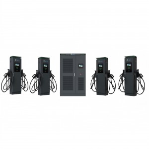
600kW Liquid-Cooled Split DC Fast Charger for P...
-

7kw 20kw CCS2 Gb/T Dc Movable Portable Dc Fast ...
-
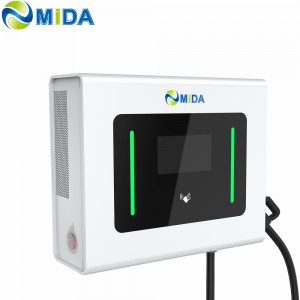
CCS2 GBT CCS2 DC Wall-mounted Charger Station D...
-
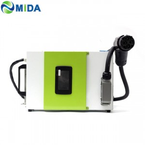
ev portable charger 15 kw ev dc fast charger cc...